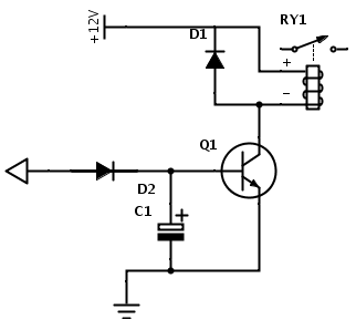
This transistor biasing current should maximum of 5mA. Working Explanation. The areas of operation for a transistor switch are acknowledged as the Saturation Region and the Cut-off Region. When we press the push button a small amount of current entered in the base of the transistor which turns it ON when we release the push button the base current is no more present so a transistor will enter into its cut-off region and finally turned OFF. Proper voltage supply is known as biasing.
The input signal is amplified at the base and then transferred to the emitter. As discussed a transistor will act as an Open switch during Forward Bias and as a Closed switch during Reverse Bias, this biasing can be achieved by supplying the required amount of current to the base pin. NPN transistors are wont to “switch ground” on a tool, meaning, they’ve placed once the load during.
The base terminal of the Qtransistor will be pulled downwar and then LLED will blink to indicate power is ON. Planet Arduino is, or at the moment is wishing to become, an aggregation of public weblogs from around the world written by people who develop, play, think on Arduino platform and his son. The opinions expressed in those weblogs and hence this aggregation are those of the original authors. Entries on this page are owned by their authors.

A transistor acts as an Open switch during forwarding and as a Closed switch during Reverse Bias, this biasing can only be achieved by supplying the required amount of current to the base pin of the transistor. Learn Arduino , Lesson 13. The small DC motor, is likely to use more power than an Arduino digital output can handle directly.
The text of the Arduino reference is licensed under a Creative Commons Attribution-ShareAlike 3. Step 2: Now take a Soldering Iron and then pre tin the Legs of the Soldering Iron. Step 3: Now you will need a 10K resistor. Step 4: Now, You will need a 100uF Capacitor. With this simple automatic street light control system, we can control a 230v street light using a relay. The 2volt AC bulb will automatically turn on after the sunset and turn off after sunrise.
The speaker is connected with NPN transistor BC547. It has three terminals namely emitter, base, and collector. The amount of current flowing from base to the emitter controls the amount of the current flowing through the collector.
When the button is pressed the fan will turn ON and will remain in this state until the button is pressed again. Bc5arduino Arduino -for - Große Auswahl an Arduino -fo. Finde Arduino -for! Kostenloser Versand verfügbar.

Thanks for contributing an answer to Arduino Stack Exchange! Please be sure to answer the question. Provide details and share your research! But avoid … Asking for help, clarification, or responding to other. BC5has a gain value of 1to 800.
That would be a way to kill the Arduino board in no time flat. In this project, I will show you how you can use a simple and cheap transistor to control your motor. Then Connect the 10k Resistor with the Transistor’s Collector and the base Pin.
Check out simple Arduino tutorials that will help you understand how Arduino is working and how to write code for it. It is kind of an NPN transistor. In this quick Arduino tutorial I will explain how you can control a relay using the Arduino Boar one 1K and one 10K resistors, BC5transistor, one 6V.
Besides these uses it can also be used in commercial circuits. It comes in TO-packaging and the maximum output current this transistor can handle is 100mA. Follow their code on GitHub.
Inga kommentarer:
Skicka en kommentar